Create a basic ESP32 ADC Library in the ESP-IDF C++
The ESP32 features a SAR ADC or a Successive Approximation ADC. The ADC can be used to measure analog inputs for example to measure a voltage or even to record audio.
In this tutorial, we are going to create a C++ wrapper class that will:
- Set a pin as an analog input with some default settings
- Check if the calibration fuse has been set
- Change the attenuation and bit_width
- Take single ADC readings
- Privide the measured value in millivolts if the calibration fuse has been set
The library that we are going to create in this tutorial is not an extensive library, however, we are going to add additional features and functionality to this library in future tutorials.
Basic ESP32 ADC C++ library
Create new project
The easiest way to create a new project in VS Code for the ESP-IDF is to open the command palette by pressing ctrl+shift+P and typing ESP-IDF: Show Examples Projects and then selecting Sample Project from the list.
This will create all of the configuration files for your setup.
When the project has been created we need to close the project by clicking on File and then Close Folder.
Now navigate to where the project has been created and rename the folder named sample_project to CPPANALOGIO. Be careful not to add spaces in the folder name.
We are now going to restructure the folder a bit and create some new files. For more information on creating a project for C++ please see this tutorial: ESP-IDF C++ with CMake for ESP32.
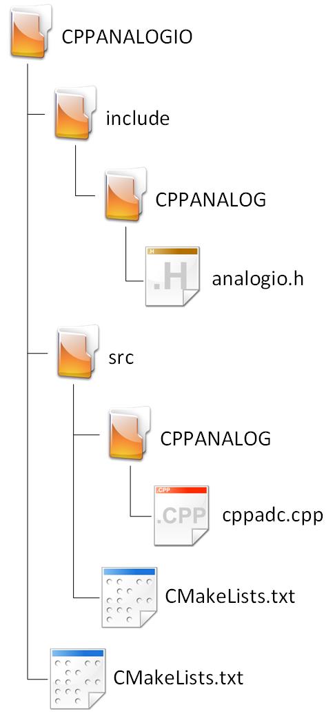
Change the folder structure and add files and folders so that the project looks like the following:
Project Structure
I’m only showing the folder that we created. There will be several more that the Sample Project template has created.
This will be another library to be reusable in future projects that will make use of the ADC so the project will only have the include and src folders.
The CmakeLists.txt files are also going to change when we integrate the libraries into other projects, however for now we are going to keep it like this in order to develop and test it as stand-alone projects.
Configure CMake
Change the content of CMakeLists.txt in the project root to the following:
# For more information about build system see
# https://docs.espressif.com/projects/esp-idf/en/latest/api-guides/build-system.html
# The following five lines of boilerplate have to be in your project's
# CMakeLists in this exact order for cmake to work correctly
cmake_minimum_required(VERSION 3.8)
set(CMAKE_CXX_STANDARD 17)
set(EXTRA_COMPONENT_DIRS src include)
include($ENV{IDF_PATH}/tools/cmake/project.cmake)
project(CPPANALOGIO)
Now change the content of CmakeLists.txt in the src folder to the following:
set(SOURCES main.cpp
            CPPANALOG/cppadc.cpp)

idf_component_register(SRCS ${SOURCES}
                    INCLUDE_DIRS .  ../include/CPPANALOG
                    REQUIRES "esp_adc_cal")
One addition here is REQUIRES “esp_adc_cal”. If we do not add this here then we will get an error that “esp_adc_cal.h” cannot be found when we try to include it.
This concludes the Cmake configuration for this project. The project is not configured to use C++ 17 and all the header files will be found and source files will resolve.
Define the ADC class in the header
Open up analogio.h in the include\CPPANALOG folder and add the following code:
#pragma once

#include "driver/adc.h"
#include "esp_adc_cal.h"

// ADC Calibration
#if CONFIG_IDF_TARGET_ESP32
constexpr static const esp_adc_cal_value_t ADC_CALI_SCHEME = ESP_ADC_CAL_VAL_EFUSE_VREF;
#elif CONFIG_IDF_TARGET_ESP32S2
constexpr static const esp_adc_cal_value_t ADC_CALI_SCHEME = ESP_ADC_CAL_VAL_EFUSE_TP;
#elif CONFIG_IDF_TARGET_ESP32C3
constexpr static const esp_adc_cal_value_t ADC_CALI_SCHEME = ESP_ADC_CAL_VAL_EFUSE_TP;
#elif CONFIG_IDF_TARGET_ESP32S3
constexpr static const esp_adc_cal_value_t ADC_CALI_SCHEME = ESP_ADC_CAL_VAL_EFUSE_TP_FIT;
#endif

namespace CPPANALOG
{
    class CppAdc1
    {
        private:
            adc_bits_width_t _bitWidth = ADC_WIDTH_BIT_12;
            adc1_channel_t _adc1Channel;
            adc_atten_t _adcAttenuation = ADC_ATTEN_DB_11;
            bool _calEnabled = false;
            esp_adc_cal_characteristics_t _adc1_characteristics;
            bool _checkCalFuse();

        public:
            CppAdc1(void);
            CppAdc1(adc1_channel_t channel);
            void SetChannel(adc1_channel_t channel);
            esp_err_t SetBitWidth(adc_bits_width_t bitWidth);
            esp_err_t SetBitWidth(int bitWidth);
            esp_err_t SetAttenuation(adc_atten_t attenuation);

            bool CheckCalFuse();
            int GetRaw();
            int GetVoltage();
    }; // CppAdc Class
} // CPPANALOG namespace
Let’s take a closer look at the parts:
#pragma once

#include "driver/adc.h"
#include "esp_adc_cal.h"
This is the guard to ensure that the same header is not included twice and also the includes.
#if CONFIG_IDF_TARGET_ESP32
constexpr static const esp_adc_cal_value_t ADC_CALI_SCHEME = ESP_ADC_CAL_VAL_EFUSE_VREF;
#elif CONFIG_IDF_TARGET_ESP32S2
constexpr static const esp_adc_cal_value_t ADC_CALI_SCHEME = ESP_ADC_CAL_VAL_EFUSE_TP;
#elif CONFIG_IDF_TARGET_ESP32C3
constexpr static const esp_adc_cal_value_t ADC_CALI_SCHEME = ESP_ADC_CAL_VAL_EFUSE_TP;
#elif CONFIG_IDF_TARGET_ESP32S3
constexpr static const esp_adc_cal_value_t ADC_CALI_SCHEME = ESP_ADC_CAL_VAL_EFUSE_TP_FIT;
#endif
Here we set the ADC calibration schema based on what device is configured to be used. Many examples will use the #DEFINE directive. I use the constexpr because it is strongly typed.
        private:
            adc_bits_width_t _bitWidth = ADC_WIDTH_BIT_12;
            adc1_channel_t _adc1Channel;
            adc_atten_t _adcAttenuation = ADC_ATTEN_DB_11;
            bool _calEnabled = false;
            esp_adc_cal_characteristics_t _adc1_characteristics;
            bool _checkCalFuse();
This is all of the private variables and methods:
- _bitWidth: Variable to hold the Bit Width confuguration. The Bit Width determines the resulution of the raw ADC value. I set the default here to 12 bits with gives us 4096 steps.
- _adc1Channel: Holds the ADC Channel to be used. I named it ADC1, becasue ADC1 and ADC2 are seperate in the ESP32. I did not include ADC2 becasue most of the ADC2 pins cannot be used if the WiFi is enabled.
- _adcAttenuation: This hold the attenuation value. The ESP32 ADC used an internal reference voltage of about 1.1V. In order to accepts input voltage levels higher than 1.1V the signal is sent through a voltage devider which can be set using this variable.
- _calEnabled: A boolean variable that is set if the ESP32 ADC have been calibrated.
- _adc1_characteristics: This variable holds the calibration data if the ESP32 have been calibrated.
- _checkCalFuse(): This method will check if the ESP32 has been calibrated and assign _adc1_characteristics to ADC1.
        public:
            CppAdc1(void);
            CppAdc1(adc1_channel_t channel);
            esp_err_t SetBitWidth(adc_bits_width_t bitWidth);
            esp_err_t SetBitWidth(int bitWidth);
            esp_err_t SetAttenuation(adc_atten_t attenuation);

            bool CheckCalFuse();
            int GetRaw();
            int GetVoltage();
These are all the public methods. Let’s take a closer look:
CppAdc1(void);
CppAdc1(adc1_channel_t channel);
These are the constructors for the class.
void SetChannel(adc1_channel_t channel);A method to set the ADC channel later if not done with the constructor.
esp_err_t SetBitWidth(adc_bits_width_t bitWidth);
esp_err_t SetBitWidth(int bitWidth);
Methods to set the bit width. I overloaded it to have 2 options so that the user can use integers as arguments.
esp_err_t SetAttenuation(adc_atten_t attenuation);
esp_err_t SetAttenuation(int attenuation);
Methods to set the attenuation. I overloaded it to have 2 options so that the user can use integers as arguments.
bool CheckCalFuse();This method can be used to tell the user whether or not the calibration fuse has been set or not.
int GetRaw();
int GetVoltage();
Methods to get either the raw ADC value (0 – 4095 depending on bit width) or to get the voltage on the ADC pin.
Implement the ADC Class methods
Open up cppadc.cpp in the src\CPPANALOG folder and add the following code:
#include "analogio.h"

namespace CPPANALOG
{
    bool CppAdc1::_checkCalFuse()
    {
        esp_err_t status {ESP_OK};
        bool cali_enable = false;

        status = esp_adc_cal_check_efuse(ADC_CALI_SCHEME);
        if (ESP_OK == status)
        {
            cali_enable = true;
            esp_adc_cal_characterize(ADC_UNIT_1, _adcAttenuation, _bitWidth, 0, &_adc1_characteristics);
        }
        return cali_enable;
    }

    CppAdc1::CppAdc1(void)
    {
    }

    CppAdc1::CppAdc1(adc1_channel_t channel)
    {
        SetChannel(channel);
    }

    void CppAdc1::SetChannel(adc1_channel_t channel)
    {
        _adc1Channel = channel;
        adc1_config_width(_bitWidth);
        adc1_config_channel_atten(_adc1Channel, _adcAttenuation);

        _calEnabled = _checkCalFuse();
    }

    bool CppAdc1::CheckCalFuse()
    {
        return _checkCalFuse();
    }

    int CppAdc1::GetRaw()
    {
        return adc1_get_raw(_adc1Channel);
    }

    int CppAdc1::GetVoltage()
    {
        if(_calEnabled)
        {
            return esp_adc_cal_raw_to_voltage(adc1_get_raw(_adc1Channel), &_adc1_characteristics);
        }
        else
        {
            return -1;
        }
    }

    esp_err_t CppAdc1::SetBitWidth(adc_bits_width_t bitWidth)
    {
        _bitWidth = bitWidth;
        _calEnabled = _checkCalFuse();
        return adc1_config_width(_bitWidth);
    }

    esp_err_t CppAdc1::SetBitWidth(int bitWidth)
    {
        switch (bitWidth)
        {
        case 9:
            _bitWidth = ADC_WIDTH_BIT_9;
            break;
        case 10:
            _bitWidth = ADC_WIDTH_BIT_10;
            break;
        case 11:
            _bitWidth = ADC_WIDTH_BIT_11;
            break;
        case 12:
            _bitWidth = ADC_WIDTH_BIT_12;
            break;
        default:
            _bitWidth = ADC_WIDTH_BIT_12;
            break;
        }
        _calEnabled = _checkCalFuse();
        return adc1_config_width(_bitWidth);
    }

    esp_err_t CppAdc1::SetAttenuation(adc_atten_t attenuation)
    {
        _adcAttenuation = attenuation;
        _calEnabled = _checkCalFuse();
        return adc1_config_channel_atten(_adc1Channel, _adcAttenuation);
    }

} // CPPANALOG namespace
Let’s take a closer look at each method:
    bool CppAdc1::_checkCalFuse()
    {
        esp_err_t status {ESP_OK};
        bool cali_enable = false;

        status = esp_adc_cal_check_efuse(ADC_CALI_SCHEME);
        if (ESP_OK == status)
        {
            cali_enable = true;
            esp_adc_cal_characterize(ADC_UNIT_1, _adcAttenuation, _bitWidth, 0, &_adc1_characteristics);
        }
        return cali_enable;
    }
This method checks if the calibration fuse has been set. If the fuse has been set then calibration characteristics will be set and the method will return true as a boolean. If the calibration fuse has not been set then the method will return false.
    CppAdc1::CppAdc1(void)
    {
    }

    CppAdc1::CppAdc1(adc1_channel_t channel)
    {
        SetChannel(channel);
    }

    void CppAdc1::SetChannel(adc1_channel_t channel)
    {
        _adc1Channel = channel;
        adc1_config_width(_bitWidth);
        adc1_config_channel_atten(_adc1Channel, _adcAttenuation);

        _calEnabled = _checkCalFuse();
    }
These are the implementations of the class constructors and the method to set the channel. When a channel is set several default states are assigned. These states can be changed at any time.
    bool CppAdc1::CheckCalFuse()
    {
        return _checkCalFuse();
    }
This method returns the status of the calibration fuse. It is useful if the user wants to check if the fuse has been set.
This method can also be used if you want to implement a procedure to manually calibrate the ADC if the fuse has not been set by the factory.
    int CppAdc1::GetRaw()
    {
        return adc1_get_raw(_adc1Channel);
    }
This method returns the raw ADC value as an integer value with a range dependent on the bit width:
- 9: 0 – 511
- 10: 0 – 1023
- 11: 0 – 2047
- 12: 0 – 4095
    int CppAdc1::GetVoltage()
    {
        if(_calEnabled)
        {
            return esp_adc_cal_raw_to_voltage(adc1_get_raw(_adc1Channel), &_adc1_characteristics);
        }
        else
        {
            return -1;
        }
    }
This method checks if the calibration fuse is set and the calibration data loaded into the ADC. If it has been, then it returns the voltage value on the ADC pin in millivolts. If the calibration bit has not been set then this method returns -1.
    esp_err_t CppAdc1::SetBitWidth(adc_bits_width_t bitWidth)
    {
        _bitWidth = bitWidth;
        _calEnabled = _checkCalFuse();
        return adc1_config_width(_bitWidth);
    }

    esp_err_t CppAdc1::SetBitWidth(int bitWidth)
    {
        switch (bitWidth)
        {
        case 9:
            _bitWidth = ADC_WIDTH_BIT_9;
            break;
        case 10:
            _bitWidth = ADC_WIDTH_BIT_10;
            break;
        case 11:
            _bitWidth = ADC_WIDTH_BIT_11;
            break;
        case 12:
            _bitWidth = ADC_WIDTH_BIT_12;
            break;
        default:
            _bitWidth = ADC_WIDTH_BIT_12;
            break;
        }
        _calEnabled = _checkCalFuse();
        return adc1_config_width(_bitWidth);
    }
these are the methods to set the ADC bit width. This first method accepts an adc_bits_width_t datatype which can be used directly with the adc1_config_width API call. It is not as intuitive though.
The second implementation accepts an integer as an argument. This is more intuitive as die number of bits can be entered as an argument. The switch statement assigned the correct value to the correct datatype.
    esp_err_t CppAdc1::SetAttenuation(adc_atten_t attenuation)
    {
        _adcAttenuation = attenuation;
        _calEnabled = _checkCalFuse();
        return adc1_config_channel_atten(_adc1Channel, _adcAttenuation);
    }
These methods set the attenuation.
Read some ADC Values
Create the test circuit
On a breadboard create the following circuit:
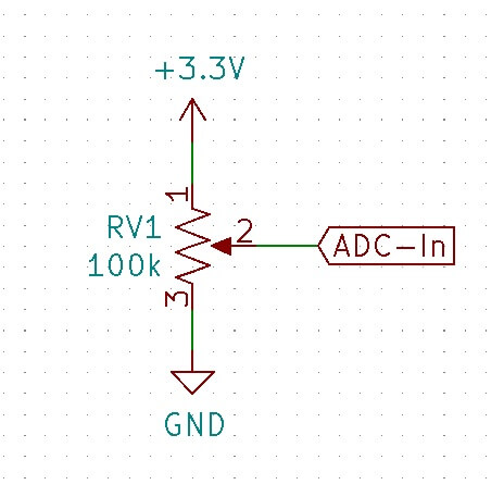
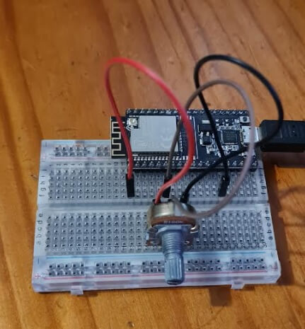
Connect ADC-In to GPIO pin 35
main.h
Copy the following code into main.h in the src folder:
#pragma once

#include "freertos/FreeRTOS.h"
#include "freertos/task.h"
#include <iostream>
#include "analogio.h"

class Main final
{
public:
    void run(void);
    void setup(void);

    CPPANALOG::CppAdc1 ADC{ADC1_CHANNEL_7}; // pin 35

}; // Main Class
It’s not really intuitive that ADC1_CHANNEL_7 is pin 35, we might adjust the library in the near future to accept the pin number as an argument. That is, however, beyond the scope of this tutorial.
main.cpp
Copy the following code into main.cpp in the src folder:
#include "main.h"

Main App;

void Main::run(void)
{
    std::cout << "Raw Data: " << ADC.GetRaw() << '\n';
    std::cout << "Calibrated voltage: " << ADC.GetVoltage() << "mV\n";
}

void Main::setup(void)
{
    ADC.SetBitWidth(12);
}

extern "C" void app_main(void)
{
    App.setup();
     while (true)
    {
        vTaskDelay(pdMS_TO_TICKS(1000));
        App.run();
    }
}
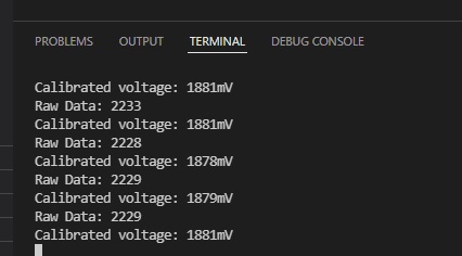
Run the program
You can now compile the project and upload the program to your ESP32 device. The output should look similar to the following:
Conclusion
We have created an ADC class to easily read a single ADC value. The library is not extensive and has some room for improvements and additions. We will be added to this library in future tutorials to add additional functionality and make some quality of life adjustments.
To download this project from Github, click here.
Thanks for reading.