Basic ESP32 DAC C++ library
Create a basic ESP32 DAC Library in the ESP-IDF C++
The ESP32 features 2 Digital to Analog Converters (DAC) channels. These can be used to stream audio and other data streams using I2S, or they can be used to control voltage levels on the output pin.
The I2S feature falls outside of the scope for this tutorial, however, we are going to cover it in a future tutorial.
In this tutorial, we are going to create a wrapper class to:
- Set the output voltage of the DAC
- Output a cosine wave to the DAC
- Set the scale of the cosine wave
- Set the phase of the cosine wave
- Set the frequency of the cosine wave
- Set the offset of the cosine wave
This tutorial builds on the library that we create in the previous post: Basic ESP32 ADC C++ library It is recommended to follow that tutorial before proceeding to this one but not required. It will however be easier to follow if you have created the project.
Basic ESP32 DAC C++ library
Open the ADC project
Open the project created in the Basic ESP32 ADC C++ library tutorial. If have not done the tutorial yet, I recommend doing the tutorial before continuing this one. If you do not want to do the ADC tutorial then you can download the project here.
Please note that if you decide to download the project from Github, you will need to create a new sample project, rename the folder to CPPANALOGIO and add the downloaded files. Do not delete the .devcontainer or .vscode folders.
Define the DAC class in the header
Open up analogio.h in the include\CPPANALOG folder and add the following code:
#include "driver/dac.h" // DAC channel 1 is GPIO25(ESP32) / GPIO17(ESP32S2)
// DAC channel 2 is GPIO26(ESP32) / GPIO18(ESP32S2)
class CppDac
{
private:
dac_channel_t _channel;
dac_cw_config_t _cosine_wave_config;
esp_err_t _init(dac_channel_t channel);
public:
CppDac(void);
CppDac(dac_channel_t channel);
esp_err_t SetChannel(dac_channel_t channel);
esp_err_t SetVoltageByValue(uint8_t level);
esp_err_t SetVoltage(float voltage);
esp_err_t DacEnable(void);
esp_err_t DacDisable(void);
esp_err_t DacCsEnable(void);
esp_err_t DaCsDisable(void);
esp_err_t SetCsScale(dac_cw_scale_t scale);
esp_err_t SetCsPhase(dac_cw_phase_t phase);
esp_err_t SetCsFrequency(uint32_t freq);
esp_err_t SetCsOffset(int8_t offset);
esp_err_t SetCsConfig(dac_cw_scale_t scale, dac_cw_phase_t phase, uint32_t freq, int8_t offset);
}; // CppDac ClassThe complete code in analogio.h should now look like this:
#pragma once
#include "driver/adc.h"
#include "driver/dac.h"
#include "esp_adc_cal.h"
// ADC Calibration
#if CONFIG_IDF_TARGET_ESP32
constexpr static const esp_adc_cal_value_t ADC_CALI_SCHEME = ESP_ADC_CAL_VAL_EFUSE_VREF;
#elif CONFIG_IDF_TARGET_ESP32S2
constexpr static const esp_adc_cal_value_t ADC_CALI_SCHEME = ESP_ADC_CAL_VAL_EFUSE_TP;
#elif CONFIG_IDF_TARGET_ESP32C3
constexpr static const esp_adc_cal_value_t ADC_CALI_SCHEME = ESP_ADC_CAL_VAL_EFUSE_TP;
#elif CONFIG_IDF_TARGET_ESP32S3
constexpr static const esp_adc_cal_value_t ADC_CALI_SCHEME = ESP_ADC_CAL_VAL_EFUSE_TP_FIT;
#endif
namespace CPPANALOG
{
class CppAdc1
{
private:
adc_bits_width_t _bitWidth = ADC_WIDTH_BIT_12;
adc1_channel_t _adc1Channel;
adc_atten_t _adcAttenuation = ADC_ATTEN_DB_11;
bool _calEnabled = false;
esp_adc_cal_characteristics_t _adc1_characteristics;
bool _checkCalFuse();
public:
CppAdc1(void);
CppAdc1(adc1_channel_t channel);
void SetChannel(adc1_channel_t channel);
esp_err_t SetBitWidth(adc_bits_width_t bitWidth);
esp_err_t SetBitWidth(int bitWidth);
esp_err_t SetAttenuation(adc_atten_t attenuation);
bool CheckCalFuse();
int GetRaw();
int GetVoltage();
}; // CppAdc Class
    // DAC channel 1 is GPIO25(ESP32) / GPIO17(ESP32S2)
    // DAC channel 2 is GPIO26(ESP32) / GPIO18(ESP32S2)
    class CppDac
    {
        private:
            dac_channel_t _channel;
            dac_cw_config_t _cosine_wave_config;
            esp_err_t _init(dac_channel_t channel);
        public:
            CppDac(void);
            CppDac(dac_channel_t channel);
            esp_err_t SetChannel(dac_channel_t channel);
            esp_err_t SetVoltageByValue(uint8_t level);
            esp_err_t SetVoltage(float voltage);
            esp_err_t DacEnable(void);
            esp_err_t DacDisable(void);
            esp_err_t DacCsEnable(void);
            esp_err_t DaCsDisable(void);
            esp_err_t SetCsScale(dac_cw_scale_t scale);
            esp_err_t SetCsPhase(dac_cw_phase_t phase);
            esp_err_t SetCsFrequency(uint32_t freq);
            esp_err_t SetCsOffset(int8_t offset);
            esp_err_t SetCsConfig(dac_cw_scale_t scale, dac_cw_phase_t phase, uint32_t freq, int8_t offset);
    }; // CppDac Class
} // CPPANALOG namespaceLet’s take a look at the new code that we added:
#include "driver/dac.h"We need to include API for the ESP-IDF DAC driver.
class CppDacWe are defining a new class named CppDac. We will use this to create objects of CppAdc type to easily use the DAC functions.
        private:
            dac_channel_t _channel;
            dac_cw_config_t _cosine_wave_config;
            esp_err_t _init(dac_channel_t channel);
We declare 2 private variables and one private method:
- _channel: Private variable to hold the DAC channel for the object
- _cosine_wave_config: Private variable thatt will hold the configuration data for the cosine wave
- _init: Private method to initialize the cosine generator to a default state.
        public:
            CppDac(void);
            CppDac(dac_channel_t channel);
            esp_err_t SetChannel(dac_channel_t channel);
            esp_err_t SetVoltageByValue(uint8_t level);
            esp_err_t SetVoltage(float voltage);
            esp_err_t DacEnable(void);
            esp_err_t DacDisable(void);
            esp_err_t DacCsEnable(void);
            esp_err_t DaCsDisable(void);
            esp_err_t SetCsScale(dac_cw_scale_t scale);
            esp_err_t SetCsPhase(dac_cw_phase_t phase);
            esp_err_t SetCsFrequency(uint32_t freq);
            esp_err_t SetCsOffset(int8_t offset);
            esp_err_t SetCsConfig(dac_cw_scale_t scale, dac_cw_phase_t phase, uint32_t freq, int8_t offset);
We have 2 constructors and 12 public methods to cover the full functionality of the DAC minus I2S. Here is what each of the methods is responsible for:
- CppDac: The contructors. Can accept the DAC channel as an argument to initialize when the object is created or can be left empty to assign the channel later.
- SetChannel: If the channel was not set in the constructor then it can be set using this method.
- SetVoltageByValue: Set the DAC output level by passing a value from 0 up to 255
- SetVoltage: Set the DAC output value by specifying a voltage level
- DacEnable: Enable a voltage level output
- DacDisable: Disable a voltage level output
- DacCsEnable: Enable the cosine wave generator output
- DaCsDisable: Disable the cosine wave generator output
- SetCsScale: Set the scale for the cosine wave generator
- SetCsPhase: Set the phase for the cosine wave generator
- SetCsFrequency: Set the frequency for the cosine wave generator
- SetCsOffset: Set the offset for the cosine wave generator
- SetCsConfig: Set all configuration options for the cosine wave generator in one method.
Implement the ADC Class methods
Open up cppdac.cpp in the src\CPPANALOG folder and add the following code:
#include "analogio.h"

namespace CPPANALOG
{
    esp_err_t CppDac::_init(dac_channel_t channel)
    {
        _channel = channel;

        // Set default values for cosine wave generator
        _cosine_wave_config.en_ch = channel;
        _cosine_wave_config.scale = DAC_CW_SCALE_1;
        _cosine_wave_config.phase = DAC_CW_PHASE_0;
        _cosine_wave_config.freq = 1000;
        _cosine_wave_config.offset = 0;

        return dac_cw_generator_config(&_cosine_wave_config);
    }

    CppDac::CppDac(void)
    {
    }

    CppDac::CppDac(dac_channel_t channel)
    {
        _init(channel);
    }

    esp_err_t CppDac::SetChannel(dac_channel_t channel)
    {
        _init(channel);

        return ESP_OK;
    }

    esp_err_t CppDac::SetVoltageByValue(uint8_t level)
    {
        esp_err_t status = ESP_OK;

        status |= DaCsDisable();
        status |= DacEnable();
        status |= dac_output_voltage(_channel, level);

        return status;
    }

    esp_err_t CppDac::SetVoltage(float voltage)
    {

        esp_err_t status = ESP_OK;
        uint8_t level = 0;

        if (voltage < 0)
        {
            voltage = 0;
        }
        if (voltage > 3.3)
        {
            voltage = 3.3;
        }

        level = voltage * 77.27; // 255/3.3 = 77.27

        status |= DaCsDisable();
        status |= DacEnable();
        status |= dac_output_voltage(_channel, level);

        return status;
    }

    esp_err_t CppDac::DacEnable(void)
    {
        return dac_output_enable(_channel);
    }

    esp_err_t CppDac::DacDisable(void)
    {
        return dac_output_disable(_channel);
    }

    esp_err_t CppDac::DacCsEnable(void)
    {
        esp_err_t status = ESP_OK;
        // status |= DacDisable();
        status |= dac_cw_generator_enable();

        return status;
    }

    esp_err_t CppDac::DaCsDisable(void)
    {
        return dac_cw_generator_disable();
    }

    esp_err_t CppDac::SetCsScale(dac_cw_scale_t scale)
    {
        _cosine_wave_config.scale = scale;

        return dac_cw_generator_config(&_cosine_wave_config);
    }

    esp_err_t CppDac::SetCsPhase(dac_cw_phase_t phase)
    {
        _cosine_wave_config.phase = phase;

        return dac_cw_generator_config(&_cosine_wave_config);
    }

    esp_err_t CppDac::SetCsFrequency(uint32_t freq)
    {
        if(freq < 130)
        {
            freq = 130;
        }
        if (freq > 55000)
        {
            freq = 55000;
        }
        _cosine_wave_config.freq = freq;

        return dac_cw_generator_config(&_cosine_wave_config);
    }

    esp_err_t CppDac::SetCsOffset(int8_t offset)
    {
        _cosine_wave_config.offset = offset;

        return dac_cw_generator_config(&_cosine_wave_config);
    }

    esp_err_t CppDac::SetCsConfig(dac_cw_scale_t scale, dac_cw_phase_t phase, uint32_t freq, int8_t offset)
    {
        if(freq < 130)
        {
            freq = 130;
        }
        if (freq > 55000)
        {
            freq = 55000;
        }

        _cosine_wave_config.scale = scale;
        _cosine_wave_config.phase = phase;
        _cosine_wave_config.freq = freq;
        _cosine_wave_config.offset = offset;

        return dac_cw_generator_config(&_cosine_wave_config);
    }
} // CPPANALOG namespace
Let us take a look at the individual methods:
    esp_err_t CppDac::_init(dac_channel_t channel)
    {
        _channel = channel;

        // Set default values for cosine wave generator
        _cosine_wave_config.en_ch = channel;
        _cosine_wave_config.scale = DAC_CW_SCALE_1;
        _cosine_wave_config.phase = DAC_CW_PHASE_0;
        _cosine_wave_config.freq = 1000;
        _cosine_wave_config.offset = 0;

        return dac_cw_generator_config(&_cosine_wave_config);
    }
This method sets the _channel variable to the channel provided by the user. Then it assigns some default states to the cosine wave generator and sets the configuration.
- scale: Set the Amplitude of the cosine wave with reference to VDD3P3_RTC. The available options are: 1/1, 1/2, 1/4 & 1/8. We set the default to 1/1.
- phase: Set the phase of the cosine wave. The only available options are 0° and 180°. We set the default to 0°
- freq: Set the frequency of the cosine wave. The frequency can be anything from 130Hz up to 55KHz
- offset: set the offset of the cosine wave. Valid settings for the offset is from -128 up to 127. Depending on what the scale is set to, the sine wave can be saturated (chopped) if unreasonable values are selected here.
    CppDac::CppDac(void)
    {
    }

    CppDac::CppDac(dac_channel_t channel)
    {
        _init(channel);
    }
The constructors for the class. If the DAC channel is not provided when an object of the class is created, then nothing is done. If the DAC channel is provided then the _init method is called with the DAC channel as the argument.
    esp_err_t CppDac::SetChannel(dac_channel_t channel)
    {
        _init(channel);

        return ESP_OK;
    }
If the DAC channel is not provided when an object of the class is created, then this method must be used to assign a channel to the object.
    esp_err_t CppDac::SetVoltageByValue(uint8_t level)
    {
        esp_err_t status = ESP_OK;

        status |= DaCsDisable();
        status |= DacEnable();
        status |= dac_output_voltage(_channel, level);

        return status;
    }
This method sets the output level of the DAC by using an unsigned integer value between 0 and 255. This is useful when working with raw data.
    esp_err_t CppDac::SetVoltage(float voltage)
    {

        esp_err_t status = ESP_OK;
        uint8_t level = 0;

        if (voltage < 0)
        {
            voltage = 0;
        }
        if (voltage > 3.3)
        {
            voltage = 3.3;
        }

        level = voltage * 77.27; // 255/3.3 = 77.27

        status |= DaCsDisable();
        status |= DacEnable();
        status |= dac_output_voltage(_channel, level);

        return status;
    }
This method sets the output of the DAC to approximately the voltage provided.
The input variable received as the argument is multiplied by 77.27 and then the decimals are discarded to get the nearest integer between 0 and 255 which will then be used to set the output level of the DAC.
We do some checks to ensure that the voltage level is within a valid range. If the input voltage is out of range then we set the voltage to either the minimum or the maximum depending on whether the specified voltage was too low or too high.
    esp_err_t CppDac::DacEnable(void)
    {
        return dac_output_enable(_channel);
    }

    esp_err_t CppDac::DacDisable(void)
    {
        return dac_output_disable(_channel);
    }

    esp_err_t CppDac::DacCsEnable(void)
    {
        esp_err_t status = ESP_OK;
        // status |= DacDisable();
        status |= dac_cw_generator_enable();

        return status;
    }

    esp_err_t CppDac::DaCsDisable(void)
    {
        return dac_cw_generator_disable();
    }
These are some control methods to enable or disable the DAC output types.
    esp_err_t CppDac::SetCsScale(dac_cw_scale_t scale)
    {
        _cosine_wave_config.scale = scale;

        return dac_cw_generator_config(&_cosine_wave_config);
    }

    esp_err_t CppDac::SetCsPhase(dac_cw_phase_t phase)
    {
        _cosine_wave_config.phase = phase;

        return dac_cw_generator_config(&_cosine_wave_config);
    }

    esp_err_t CppDac::SetCsFrequency(uint32_t freq)
    {
        if(freq < 130)
        {
            freq = 130;
        }
        if (freq > 55000)
        {
            freq = 55000;
        }
        _cosine_wave_config.freq = freq;

        return dac_cw_generator_config(&_cosine_wave_config);
    }

    esp_err_t CppDac::SetCsOffset(int8_t offset)
    {
        _cosine_wave_config.offset = offset;

        return dac_cw_generator_config(&_cosine_wave_config);
    }

    esp_err_t CppDac::SetCsConfig(dac_cw_scale_t scale, dac_cw_phase_t phase, uint32_t freq, int8_t offset)
    {
        if(freq < 130)
        {
            freq = 130;
        }
        if (freq > 55000)
        {
            freq = 55000;
        }

        _cosine_wave_config.scale = scale;
        _cosine_wave_config.phase = phase;
        _cosine_wave_config.freq = freq;
        _cosine_wave_config.offset = offset;

        return dac_cw_generator_config(&_cosine_wave_config);
    }
These are the methods to set the various configurations of the cosine wave generator. Note that we added some protection to keep the frequency within the allowable range.
Set some DAC output levels
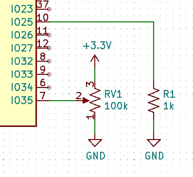
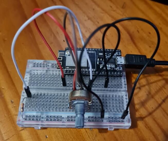
To demonstrate the DAC, we are going to read a value on the ADC through the voltage divider created in the previous tutorial and output the value on the DAC.
main.h
Copy the following code into main.h in the src folder:
#pragma once

#include "freertos/FreeRTOS.h"
#include "freertos/task.h"
#include <iostream>
#include "analogio.h"

class Main final
{
public:
    void run(void);
    void setup(void);

    CPPANALOG::CppAdc1 ADC{ADC1_CHANNEL_7}; // pin 35

    CPPANALOG::CppDac DAC{DAC_CHANNEL_1}; // pin 25

}; // Main Class
The only addition to the main.h is where we declare DAC as an object of the CppDac class that we created.
main.cpp
Copy the following code into main.cpp in the src folder:
#include "main.h"

Main App;

void Main::run(void)
{
    std::cout << "Raw Data: " << ADC.GetRaw() << '\n';
    std::cout << "Calibrated voltage: " << ADC.GetVoltage() << "mV\n";
    std::cout << "Set Output Voltage value to ADC Value: "<< (ADC.GetRaw()/16) <<'\n';
    DAC.SetVoltageByValue(ADC.GetRaw()/16);
}

void Main::setup(void)
{
    ADC.SetBitWidth(12);
}

extern "C" void app_main(void)
{
    App.setup();
     while (true)
    {
        vTaskDelay(pdMS_TO_TICKS(1000));
        App.run();
    }
}
Note the following line of code:
DAC.SetVoltageByValue(ADC.GetRaw()/16);This code sets the DAC value to whatever we read on the ADC.
We divide the raw ADC value by 16 because the ADC is set to 12 bits (0-4095) and the DAC is only 8 bits (0-255).
The output should look similar to this when you build, flash and monitor:
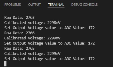
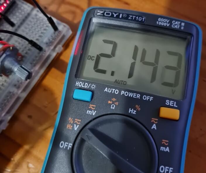
I noticed a voltage conversion error of about 150mV on my device. However, the voltage measured on the ADC input is near the same as the voltage measured at the DAC output.
To download this project from Github, click here.
Thanks for reading.