Basic ESP32 GPIO in C++
Create classes to use the ESP32 GPIO in C++
This is part 1 of a 3 part tutorial:
- ESP32 GPIO in C++ Part 1
- ESP32 GPIO in C++ Part 2
- ESP32 GPIO in C++ Part 3
In this tutorial, you are going to create wrapper classes to easily access the GPIO. We want to create classes for all the ways that we intend to use the IOs, that way we can create objects with logical names for each pin.
For this tutorial you need a VSCode installation with the ESP-IDF installed and set up for C++. The following tutorials describe how to set up the ESP-IDF in VSCode for C++.
The project created in ESP-IDF C++ with CMake for ESP32 will be used as a starting point for this tutorial.
14 June 2022 update: I’ve changed the folder structure ESP-IDF C++ with CMake for ESP32 and will no longer be using it as a base for this CPPGPIO class.
Where are we heading
The CPPGPIO project will be a multi-part tutorial with this being part 1. In this tutorial, we are only going to build the class to enable basic GPIO functionality. In part 2 of the GPIO tutorials, we are will add some more advanced features such as interrupt on input and triggering events for different inputs.
The CPPGPIO project will ultimately become a library that we will reuse in future projects.
For more information on the folder structure that I prefer to use click here
When the CPPGPIO library is completed then we are going to create an application project that is going to make use of the CPPGPIO library that we are creating now.
The reason why I am creating the library before the project is to demonstrate how libraries can be plugged into other projects and be modified as needed.
Finally are going to rename the project and make some changes to the folder structure. For now, this is a library only for GPIO, however when we create classes for other peripherals such as SPI, I2C, Timers, etc then we might want to rename the project to represent what drivers the project contains.
Then finally I will demonstrate how to create a place for libraries to be stored and references as needed by any application without having to copy the library project folders into the directory structure of the project that is going to use the library.
Create a new project
Create a new project using the instructions found here.
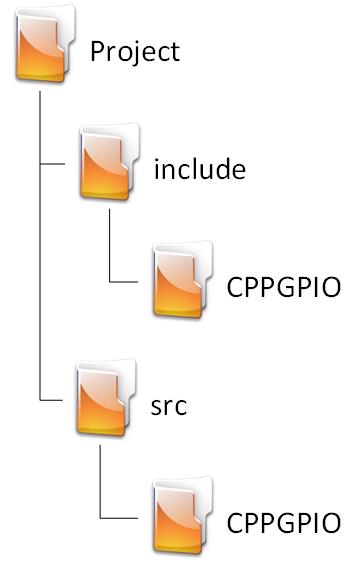
Folder Structure
This is going to be a library, not a full application so we are not going to need the main folder. Rename the folders to match the following. Leave the .vscode and .devcontainer folders unchanged.
Rename main.c in the main folder to main.cpp and move it to the src folder. Remove the main folder.
Remaining folders
Only the following folders will remain in addition to the folders that VSCode and the IDF created:
- include/CPPGPIO: Our public header comes here.
- src/CPPGPIO: The implementation of the methods defined in the public header comes in this folder.
Notice that both the source and header files are both placed in folders with the same descriptive name.
Update CMakeLists.txt
Open CMakeLists.txt in the root directory and add the following code:
# For more information about build system see
# https://docs.espressif.com/projects/esp-idf/en/latest/api-guides/build-system.html
# The following five lines of boilerplate have to be in your project's
# CMakeLists in this exact order for cmake to work correctly
cmake_minimum_required(VERSION 3.8)
set(CMAKE_CXX_STANDARD 17)
set(EXTRA_COMPONENT_DIRS src include)
include($ENV{IDF_PATH}/tools/cmake/project.cmake)
project(CPPGPIO)
This is the boilerplate that will be placed in all library projects. The only difference between this and an application project is set(EXTRA_COMPONENT_DIRS src include). In an application, we only add a components directory.
Create the GPIO Class header
Create a new file named cppgpio.h in the /include/CPPGPIO/ directory,
Many options
There are several ways to go about creating a wrapper class for GPIO, fortunately, we are not limited to choosing only one. You can create Arduino-style digitalRead and digitalWrite methods if that is more comfortable for you.
Add the includes
In cppgpio.h, write the following code:
#include "driver/gpio.h"For basic GPIO functionality, we only need this one include. We will add several more in part 2 when we introduce interrupts and events.
Add a namespace
Add the following code to cppgpio.h underneath the includes
namespace CPPGPIO
{
Even though you do not need to add a namespace, it is generally a good idea to do it anyway. The benefit of using namespaces is you do not have to worry about conflicts in variable names. This is especially useful when using third-party libraries.
Remember to close the namespace with another curly bracket at the end of the file.
Create the base class
Add the following code to cppgpio.h underneath the opening curly bracket of the namespace
class GpioBase
{
protected:
    gpio_num_t _pin;
    bool _active_low;
}; // GpioBase Class
Here we are creating a base class to hold some common variables that both the input and output classes might need. The value of this base class will become more apparent when we implement some advanced functionality.
Let us look at the individual lines:
class GpioBaseThe name of the Base class. We are not ever going to create objects of this class, The classes that will handle the input and output respectively will inherit from this class.
protected:The protected keyword has the same functionality as the private keyword with the exception that variables and methods declared as protected can be inherited.
gpio_num_t _pin;We store the IO pin that the object of this class will act on. Note the underscore (_) in front of the variable name. It is good practice to begin private variable names with an underscore. That way other developers using your code knows not to change values in those variables directly.
bool _active_low;Some pins on some devices are defined as active low. In these cases, a low represents a 1 and a high represents a 0. If we know that this is the case, then we can define the GPIO pin as active low. If implemented correctly we can then use the pin as normal and not worry about keeping track of what levels are a logical 1 and logical zero. If this is confusing, it might make more sense when we implement the functionality.
Create the Input Class
Add the following code to cppgpio.h underneath the base class:
class GpioInput : public GpioBase
{
private:
    esp_err_t _init(const gpio_num_t pin, const bool activeLow);

public:
    GpioInput(const gpio_num_t pin, const bool activeLow);
    GpioInput(const gpio_num_t pin);
    GpioInput(void);
    esp_err_t init(const gpio_num_t pin, const bool activeLow);
    esp_err_t init(const gpio_num_t pin);
    int read(void);
}; // GpioInput Class
This is the class that will read the level on a GPIO pin.
Let us take a look at each section:
class GpioInput : public GpioBaseThe class name in GpioInput and inherits from GpioBase
private:
    esp_err_t _init(const gpio_num_t pin, const bool activeLow);
the _init function is a private function of type esp_err_t. This is where we are going to initialize the GPIO pin for input. You will notice that I use esp_err_t wherever it is allowed, this is very useful for error checking and finding bugs.
Many more options can be added to the class, but for simplicity’s sake for the demonstration I’m only adding the pin number and whether or not it’s connected to an Active Low output.
GpioInput(const gpio_num_t pin, const bool activeLow);
GpioInput(const gpio_num_t pin);
GpioInput(void);
These are the 3 constructors that we are going to create for the class:
- We provide the pin number and define whether or not it is active low.
- We provide only the pin number. We will set the active low variable to a default state when we implement this constructor.
- We give no information on object declaration. We will have to initialize the object manually before use.
- This is useful if you need to allow another class to assign the GPIO number to the object.
esp_err_t init(const gpio_num_t pin, const bool activeLow);
esp_err_t init(const gpio_num_t pin);
The methods to manually initialize the GPIO for input if a constructor is not used.
int read(void);The method to return the read value on the GPIO.
Create the Output Class
Add the following code to cppgpio.h underneath the input class:
class GpioOutput : public GpioBase
    {
    private:
        int _level = 0;
        esp_err_t _init(const gpio_num_t pin, const bool activeLow);

    public:
        GpioOutput(const gpio_num_t pin, const bool activeLow);
        GpioOutput(const gpio_num_t pin);
        GpioOutput(void);
        esp_err_t init(const gpio_num_t pin, const bool activeLow);
        esp_err_t init(const gpio_num_t pin);
        esp_err_t on(void);
        esp_err_t off(void);
        esp_err_t toggle(void);
        esp_err_t setLevel(int level);
    }; // GpioOutput Class
This is the class that will set the level of a GPIO pin.
Let us take a look at each section:
class GpioOutput : public GpioBaseClass name GpioOutput which inherits from GpioBase.
int _level = 0;Private variable to keep track of the output level of the GPIO pin. The reason why I add this is because if you try to read the value of a GPIO pin configured for output it will always return 0 irrespective of what the true value might be.
esp_err_t _init(const gpio_num_t pin, const bool activeLow);This private method will initialize the GPIO pin.
GpioOutput(const gpio_num_t pin, const bool activeLow);
GpioOutput(const gpio_num_t pin);
GpioOutput(void);
These are the 3 constructors that we are going to create for the class:
- We provide the pin number and define whether or not it is active low.
- We provide only the pin number. We will set the active low variable to a default state when we implement this constructor.
- We give no information on object declaration. We will have to initialize the object manually before use.
- This is useful if you need to allow another class to assign the GPIO number to the object.
esp_err_t init(const gpio_num_t pin, const bool activeLow);
esp_err_t init(const gpio_num_t pin);
The methods to manually initialize the GPIO for output if a constructor is not used.
esp_err_t on(void);
esp_err_t off(void);
esp_err_t toggle(void);
These are the methods that will actually change the level of the GPIO pin.
esp_err_t setLevel(int level);This is a different way to set the output level of the GPIO pin. The usefulness of this method will become apparent when we test the classes created in this tutorial.
The Complete Header Code
#pragma once

#include "driver/gpio.h"

namespace CPPGPIO
{
    class GpioBase
    {
    protected:
        gpio_num_t _pin;
        bool _active_low;
    }; // GpioBase Class

    class GpioInput : public GpioBase
    {
    private:
        esp_err_t _init(const gpio_num_t pin, const bool activeLow);

    public:
        GpioInput(const gpio_num_t pin, const bool activeLow);
        GpioInput(const gpio_num_t pin);
        GpioInput(void);
        esp_err_t init(const gpio_num_t pin, const bool activeLow);
        esp_err_t init(const gpio_num_t pin);
        int read(void);
    }; // GpioInput Class

    class GpioOutput : public GpioBase
    {
    private:
        int _level = 0;
        esp_err_t _init(const gpio_num_t pin, const bool activeLow);

    public:
        GpioOutput(const gpio_num_t pin, const bool activeLow);
        GpioOutput(const gpio_num_t pin);
        GpioOutput(void);
        esp_err_t init(const gpio_num_t pin, const bool activeLow);
        esp_err_t init(const gpio_num_t pin);
        esp_err_t on(void);
        esp_err_t off(void);
        esp_err_t toggle(void);
    }; // GpioOutput Class
} // CPPGPIO Namespace
Create the GPIO Class Source
Create the source file and add it to CMake
Create a new folder in the src folder and name it CPPGPIO. Now create a new file in the new folder and name it cppgpio.cpp.
Note that now cppgpio.h and cppgpio.cpp have the same relative path from /include and /src respectively.
- /include/CPPGPIO/cppgpio.h
- /src/CPPGPIO/cppgpio.cpp
Open CMakeLists.txt in the src folder and add CPPGPIO/cppgpio.cpp next to main.cpp. The CMakeLists.txt file should now look like this:
set(SOURCES main.cpp CPPGPIO/cppgpio.cpp)
idf_component_register(SRCS ${SOURCES}
                    INCLUDE_DIRS . ../include/CPPGPIO)
If this were not intended to be a library then we would not have added /CPPGPIO after ../include.
Includes and Namespace
in the newly created cppgpio.cpp add the following lines of code:
#include "cppgpio.h"

namespace CPPGPIO
{
The only include here will be cppgpio.h. Any other files that need to be included will be included in the header file where #pragma once will protect against duplicate included headers.
The namespace must have the same name (case sensitive) in both the header and source file.
Implement the methods for the Input Class
Add the following code to cppgpio.cpp after the code created in the previous step.
    esp_err_t GpioInput::_init (const gpio_num_t pin, const bool activeLow)
    {
        esp_err_t status{ESP_OK};

        _active_low = activeLow;
        _pin = pin;

        gpio_config_t cfg;
        cfg.pin_bit_mask = 1ULL << pin;
        cfg.mode = GPIO_MODE_INPUT;
        cfg.pull_up_en = GPIO_PULLUP_DISABLE;
        cfg.pull_down_en = GPIO_PULLDOWN_DISABLE;
        cfg.intr_type = GPIO_INTR_POSEDGE;

        status |= gpio_config(&cfg);

        return status;
    }

    GpioInput::GpioInput(const gpio_num_t pin, const bool activeLow)
    {
        _init(pin, activeLow);
    }

    GpioInput::GpioInput(const gpio_num_t pin)
    {
        _init(pin, false);
    }

    GpioInput::GpioInput(void)
    {
    }

    esp_err_t GpioInput::init(const gpio_num_t pin, const bool activeLow)
    {
        return _init(pin, activeLow);
    }

    esp_err_t GpioInput::init(const gpio_num_t pin)
    {
        return _init(pin, false);
    }

    int GpioInput::read(void)
    {
        return _active_low ? !gpio_get_level(_pin) : gpio_get_level(_pin);
    }
Let us take a look at each method
Initialize
esp_err_t GpioInput::_init (const gpio_num_t pin, const bool activeLow)
    {
        esp_err_t status{ESP_OK};

        _active_low = activeLow;
        _pin = pin;

        gpio_config_t cfg;
        cfg.pin_bit_mask = 1ULL << pin;
        cfg.mode = GPIO_MODE_INPUT;
        cfg.pull_up_en = GPIO_PULLUP_DISABLE;
        cfg.pull_down_en = GPIO_PULLDOWN_DISABLE;
        cfg.intr_type = GPIO_INTR_DISABLE;

        status |= gpio_config(&cfg);

        return status;
    }
This private function initializes the pin for input. For this tutorial, we are going to assign default values for most of the available options.
Let us break down the method further:
esp_err_t status{ESP_OK};We are creating our return variable of type esp_err_t and initializing it with the value ESP_OK. If you click anywhere on ESP_OK and press F12 you will see the definitions of the error codes. ESP_OK equates to 0 which means there were no errors.
Any method that we are going to call that has a return type of esp_err_t will have its return value OR’d with status. This will enable us to check the error code(s) if anything goes wrong.
_active_low = activeLow;
_pin = pin;
Here we assign the values to our private variable.
gpio_config_t cfg;Here we are declaring a variable of type gpio_config_t. gpio_config_t is a struct that holds the configuration of the GPIO.
cfg.pin_bit_mask = 1ULL << pin;
cfg.mode = GPIO_MODE_INPUT;
cfg.pull_up_en = GPIO_PULLUP_DISABLE;
cfg.pull_down_en = GPIO_PULLDOWN_DISABLE;
cfg.intr_type = GPIO_INTR_DISABLE;
Here we assign values to all of the GPIO options. I am not enabling anything at this time, on;y setting the pin number and setting the mode to Input. Note that we can change these configurations at any time using the appropriate function calls. See the ESP-IDF documentation for more info.
You can also click on just about anything and press F12 to open the file where it is implemented. This is useful to check what options are available without having to navigate through the official ESP-IDF documentation.
status |= gpio_config(&cfg);Here we pass a pointer to the struct into gpio_config which will call all the individual functions to set up the GPIO pin. If there are no errors then the function will return ESP_OK. If there is an error then the function will return the appropriate error code for us to evaluate.
return status;We return the status variable. If there were no errors, then the method will return ESP_OK. However, if the was an error, then the appropriate error code will be returned.
Constructors and manual initialize
Add the following code underneath the _init method:
    GpioInput::GpioInput(const gpio_num_t pin, const bool activeLow)
    {
        _init(pin, activeLow);
    }

    GpioInput::GpioInput(const gpio_num_t pin)
    {
        _init(pin, false);
    }

    GpioInput::GpioInput(void)
    {
    }

    esp_err_t GpioInput::init(const gpio_num_t pin, const bool activeLow)
    {
        return _init(pin, activeLow);
    }

    esp_err_t GpioInput::init(const gpio_num_t pin)
    {
        return _init(pin, false);
    }
These constructors and methods call the _init method with the various supplied options or default values where none was supplied. Note that the constructors do not return error codes, unlike the init methods. This might be something to keep in mind when deciding how to implement this class in your code.
Implement the Read Method
Next, add the following code to cppgpio.cpp:
    int GpioInput::read(void)
    {
        return _active_low ? !gpio_get_level(_pin) : gpio_get_level(_pin);
    }
This method returns the value on the input pin. I added a shorthand if that checks if the _active_low bit is set. If the active_low bit is set, then the pin value is inverted before it is returned.
Implement the methods for the Output Class
Add the following code to cppgpio.cpp after the code created in the previous step.
    esp_err_t GpioOutput::_init(const gpio_num_t pin, const bool activeLow)
    {
        esp_err_t status{ESP_OK};

        _active_low = activeLow;
        _pin = pin;

        gpio_config_t cfg;
        cfg.pin_bit_mask = 1ULL << pin;
        cfg.mode = GPIO_MODE_OUTPUT;
        cfg.pull_up_en = GPIO_PULLUP_DISABLE;
        cfg.pull_down_en = GPIO_PULLDOWN_DISABLE;
        cfg.intr_type = GPIO_INTR_DISABLE;

        status |= gpio_config(&cfg);

        return status;
    }

    GpioOutput::GpioOutput(const gpio_num_t pin, const bool activeLow)
    {
       _init(pin, activeLow);
    }

    GpioOutput::GpioOutput(const gpio_num_t pin)
    {
        _init(pin, false);
    }

    GpioOutput::GpioOutput(void)
    {
    }

    esp_err_t GpioOutput::init(const gpio_num_t pin, const bool activeLow)
    {
        return _init(pin, activeLow);
    }

    esp_err_t GpioOutput::init(const gpio_num_t pin)
    {
        return _init(pin, false);
    }

    esp_err_t GpioOutput::on(void)
    {
        _level = true;;
        return gpio_set_level(_pin, _active_low ? 0 : 1);
    }

    esp_err_t GpioOutput::off(void)
    {
        _level = false;
        return gpio_set_level(_pin, _active_low ? 1 : 0);
    }

    esp_err_t GpioOutput::toggle(void)
    {
        _level = _level ? 0 : 1;
        return gpio_set_level(_pin, _level ? 1 : 0);
    }

    esp_err_t GpioOutput::setLevel(int level)
    {
        _level = _active_low ? !level : level;
        return gpio_set_level(_pin, _level);
    }

} // Namespace CPPGPIO
The code is very basically the same as the implementations of the Input class. The major difference is that the output methods return an error code rather than an input value.
The Complete Source Code
#include "cppgpio.h"

namespace CPPGPIO
{
    esp_err_t GpioInput::_init (const gpio_num_t pin, const bool activeLow)
    {
        esp_err_t status{ESP_OK};

        _active_low = activeLow;
        _pin = pin;

        gpio_config_t cfg;
        cfg.pin_bit_mask = 1ULL << pin;
        cfg.mode = GPIO_MODE_INPUT;
        cfg.pull_up_en = GPIO_PULLUP_DISABLE;
        cfg.pull_down_en = GPIO_PULLDOWN_DISABLE;
        cfg.intr_type = GPIO_INTR_DISABLE;

        status |= gpio_config(&cfg);

        return status;
    }

    GpioInput::GpioInput(const gpio_num_t pin, const bool activeLow)
    {
        _init(pin, activeLow);
    }

    GpioInput::GpioInput(const gpio_num_t pin)
    {
        _init(pin, false);
    }

    GpioInput::GpioInput(void)
    {
    }

    esp_err_t GpioInput::init(const gpio_num_t pin, const bool activeLow)
    {
        return _init(pin, activeLow);
    }

    esp_err_t GpioInput::init(const gpio_num_t pin)
    {
        return _init(pin, false);
    }

    int GpioInput::read(void)
    {
        return _active_low ? !gpio_get_level(_pin) : gpio_get_level(_pin);
    }

// ================================= GpioOutput ==============================
    esp_err_t GpioOutput::_init(const gpio_num_t pin, const bool activeLow)
    {
        esp_err_t status{ESP_OK};

        _active_low = activeLow;
        _pin = pin;

        gpio_config_t cfg;
        cfg.pin_bit_mask = 1ULL << pin;
        cfg.mode = GPIO_MODE_OUTPUT;
        cfg.pull_up_en = GPIO_PULLUP_DISABLE;
        cfg.pull_down_en = GPIO_PULLDOWN_DISABLE;
        cfg.intr_type = GPIO_INTR_DISABLE;

        status |= gpio_config(&cfg);

        return status;
    }

    GpioOutput::GpioOutput(const gpio_num_t pin, const bool activeLow)
    {
       _init(pin, activeLow);
    }

    GpioOutput::GpioOutput(const gpio_num_t pin)
    {
        _init(pin, false);
    }

    GpioOutput::GpioOutput(void)
    {
    }

    esp_err_t GpioOutput::init(const gpio_num_t pin, const bool activeLow)
    {
        return _init(pin, activeLow);
    }

    esp_err_t GpioOutput::init(const gpio_num_t pin)
    {
        return _init(pin, false);
    }

    esp_err_t GpioOutput::on(void)
    {
        _level = true;;
        return gpio_set_level(_pin, _active_low ? 0 : 1);
    }

    esp_err_t GpioOutput::off(void)
    {
        _level = false;
        return gpio_set_level(_pin, _active_low ? 1 : 0);
    }

    esp_err_t GpioOutput::toggle(void)
    {
        _level = _level ? 0 : 1;
        return gpio_set_level(_pin, _level ? 1 : 0);
    }

    esp_err_t GpioOutput::setLevel(int level)
    {
        _level = _active_low ? !level : level;
        return gpio_set_level(_pin, _level);
    }

} // Namespace CPPGPIO
Test the Input and Output classes
Connect button and LED
Using breadboard or other means, recreate the following circuit:
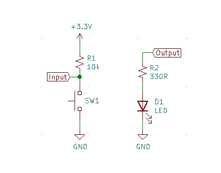
Connect the Input and Output to appropriate pins on your ESP32 device. I used the onboard LED so I only needed to connect a switch.
Create main.h
Create a new file in the src folder, name it main.h and add the following code:
#pragma once

#include "cppgpio.h"

// Main class used for testing only
class Main final
{
public:
    void run(void);

    CPPGPIO::GpioOutput cppLed { GPIO_NUM_2 };
    CPPGPIO::GpioInput cppButton { GPIO_NUM_12 };
}; // Main Class
Choose appropriate pins for your development board.
I selected pin 2 for the output because that is where the LED is connected on the NodeMCU that I have and I selected pin 12 for the input because it is convenient for me.
Modify main.cpp
Open main.cpp in the src folder and modify the code to look like this:
#include "main.h"

void Main::run(void)
{
    cppLed.setLevel(cppButton.read());
}

extern "C" void app_main(void)
{
    Main App;

    while (true)
    {
        App.run();
    }
}
You should now be able to build and flash the program to your device.
The LED should turn off when you push the button and turn on when you release it.
Testing ActiveLow
If you want to, you can change the class object declarations in main.h to enable ActiveLow for the Input, Output, or both and see how that changes the LED behavior when the button is pressed and not pressed.
To set the GPIO pins to ActiveLow, change the code in main.h to the following:
#pragma once

#include "cppgpio.h"

// Main class used for testing only
class Main final
{
public:
    void run(void);

    CPPGPIO::GpioOutput cppLed { GPIO_NUM_2, true };
    CPPGPIO::GpioInput cppButton { GPIO_NUM_12, true };
}; // Main Class
This will have the same apparent behavior as the previous block. Try to enable ActiveLow on only the input or only the output. The LED should turn on when you push the button and turn off when you release the button.
Thanks for reading.