ESP-IDF C++ I2C Driver
Create an ESP-IDF C++ I2C driver wrapper
I2C (Inter-Integrated Circuit), also known as IIC or more commonly known as I2C is a synchronous half-duplex master-slave communication protocol used in embedded systems. Officially I2C supports speeds of 100kbps and 400kbps but can be run at other speeds. Sometimes up to a few Mbps.
Unlike SPI, I2C always only has 2 lines for communications. Multiple I2C slave devices can be placed on the same I2C bus. The maximum number of slave devices is determined by the combined capacitance added by each slave device. The master will select which slave device to communicate with using a unique 7-bit long address. The 1st byte that the master sends on to an I2C bus will always be the 7-bit address and a read/write bit to make up 8 bits or 1 byte.
The data and clock lines of I2C will always be open-drain, requiring pull-up resistors for proper operation. Being open-drain makes it impossible for the master or one of the slave devices to pull the line high while another device on the bus pulls the line low which can damage the devices. There are fairly complicated formulas to optimize the value of the pull-up resistors, but as a rule of thumb 4k7 resistors will work fine in nearly all cases.
ESP-IDF I2C C++
Parts used in this tutorial
| BME280 Module | |
| NodeMCU32s | |
| Breadboard | |
| Breadboard Link Wires |
About this project
Normally I would create an I2C driver together with whatever device needs to use the I2C. That approach is not practical for a tutorial. So, I decided to create the BME280 driver, SPI driver, and I2C driver at the same time and create 3 separate tutorials for each. Then I’ll post all three tutorials at the same time and reference each as needed.
Create the component
Folder and file structure
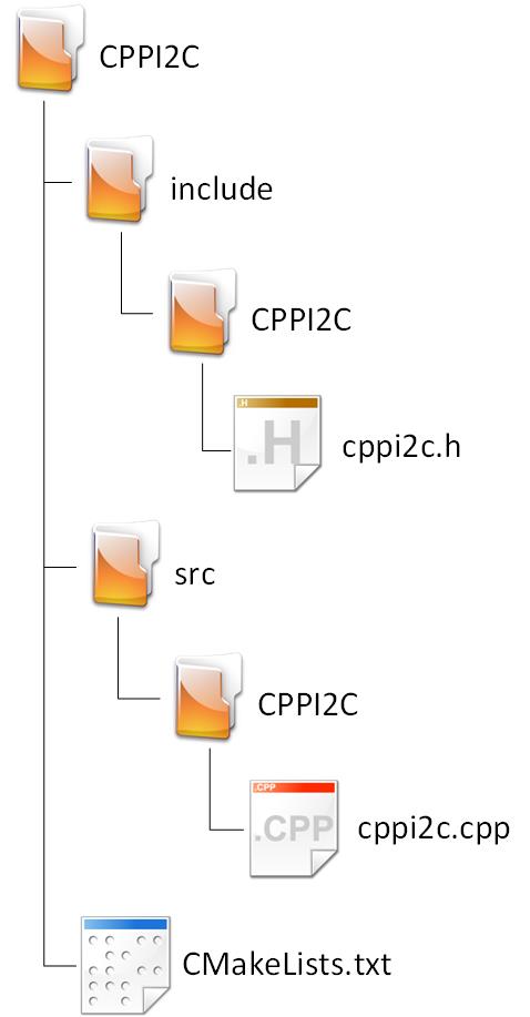
Create a folder named CPPI2C. Inside this folder create a text file named CMakeLists.txt as well as 2 folders named include and src. Inside both the src and include folders create a folder named CPPI2C, the same as the root folder name.
Now finally in the folder CPPI2C/include/CPPI2C create cppi2c.h. In CPPI2C/src/CPPI2C create cppi2c.cpp.
Configure CMakeLists.txt
Open up CMakeLists.txt in the root folder and add the following:
set(SOURCES src/CPPI2C/cppi2c.cpp)

idf_component_register(SRCS ${SOURCES}
                    INCLUDE_DIRS include)
Now any project can use this component as long as EXTRA_COMPONENT_DIRS is set properly.
Define the C++ I2C class in the header file
Open cppi2c.h in the include/CPPI2C folder and add the following code:
#pragma once

#include "driver/i2c.h"
#include "esp_intr_alloc.h"

namespace CPPI2C
{
    class I2c
    {
    private:
        uint16_t _slaveAddr{};
        i2c_port_t _port{};
        i2c_mode_t _mode{};
        size_t _slv_rx_buf_len{};
        size_t _slv_tx_buf_len{};
        int _intr_alloc_flags{};

    public:
        I2c(i2c_port_t port, size_t slv_rx_buf_len = 0, size_t slv_tx_buf_len = 0, int intr_alloc_flags = 0);
        ~I2c();

        esp_err_t InitMaster(int sda_io_num,
                             int scl_io_num,
                             uint32_t clk_speed,
                             bool sda_pullup_en = false,
                             bool scl_pullup_en = false,
                             uint32_t clk_flags = I2C_SCLK_SRC_FLAG_FOR_NOMAL);

        uint8_t ReadRegister(uint8_t dev_addr, uint8_t reg_addr);
        esp_err_t WriteRegister(uint8_t dev_addr, uint8_t reg_addr, uint8_t txData);
        esp_err_t ReadRegisterMultipleBytes(uint8_t dev_addr, uint8_t reg_addr, uint8_t *rx_data, int length);
        esp_err_t WriteRegisterMultipleBytes(uint8_t dev_addr, uint8_t reg_addr, uint8_t *tx_data, int length);
    }; // class I2c
} // namespace CPPI2C
As can be seen, the I2C class is not very large. However, there are some nuances that have the potential to cause some pain.
Let’s look at the different parts:
#pragma once

#include "driver/i2c.h"
#include "esp_intr_alloc.h"
namespace CPPI2C
{
    class I2c
    {
The normal include guard followed by the I2C driver includes. We are not going to implement I2C slave mode in this tutorial, however, we might expand this class to include slave mode in the future. include “esp_intr_alloc.h” is used to define the interrupts for I2C in slave mode. We do not need this include for this Master-only I2C implementation, however, I’m including it for future use. Note that it’s bad practice to include unused header files.
I always add my own namespace, that way I can use any class and variable names without having to worry about variable name conflicts.
    private:
        uint16_t _slaveAddr{};
        i2c_port_t _port{};
        i2c_mode_t _mode{};
        size_t _slv_rx_buf_len{};
        size_t _slv_tx_buf_len{};
        int _intr_alloc_flags{};
Many of these private variables are used only in slave mode. I’ve included them for future reference. Variables that are not used should be optimized away by the compiler (unless they are declared with the volatile keyword).
let’s look at the variables:
- _slaveAddr The slave address if used in slave mode
- _port The I2C port to use. The ESP32s have I2C port 0 and port1
- _mode Select master or slave mode
- _slv_rx_buf_len Receive buffer length used in slave mode
- _slv_tx_buf_len Transmit buffer length used in slave mode
- _intr_alloc_flags Interrupt allocation, set to 0 in master mode, I found that other values cause the I2C comms to fail.
    public:
        I2c(i2c_port_t port, size_t slv_rx_buf_len = 0, size_t slv_tx_buf_len = 0, int intr_alloc_flags = 0);
        ~I2c();

        esp_err_t InitMaster(int sda_io_num,
                             int scl_io_num,
                             uint32_t clk_speed,
                             bool sda_pullup_en = false,
                             bool scl_pullup_en = false,
                             uint32_t clk_flags = I2C_SCLK_SRC_FLAG_FOR_NOMAL);
The first of the public methods are the constructor and destructor. The constructor has default values for all the variables that are on;y needed for slave mode which is not implemented. This way an object of the class can be created by passing only the needed variable, which is the I2C port to use.
Then we have the initialization method to initialize the I2C port in master mode. Again, I provided default values for common scenarios.
        uint8_t ReadRegister(uint8_t dev_addr, uint8_t reg_addr);
        esp_err_t WriteRegister(uint8_t dev_addr, uint8_t reg_addr, uint8_t txData);
        esp_err_t ReadRegisterMultipleBytes(uint8_t dev_addr, uint8_t reg_addr, uint8_t *rx_data, int length);
        esp_err_t WriteRegisterMultipleBytes(uint8_t dev_addr, uint8_t reg_addr, uint8_t *tx_data, int length);
These 4 methods are where the magic happens. Using these methods almost any I2C communication can be accomplished.
Implement the C++ I2C class in the source file
Open cppi2c.cpp in the src/CPPI2C folder and add the following code:
#include "CPPI2C/cppi2c.h"
namespace CPPI2C
{
    I2c::I2c(i2c_port_t port, size_t slv_rx_buf_len, size_t slv_tx_buf_len, int intr_alloc_flags)
    {
        _port = port;
        _slv_rx_buf_len = slv_rx_buf_len;
        _slv_tx_buf_len = slv_tx_buf_len;
        _intr_alloc_flags = intr_alloc_flags;
    }

    I2c::~I2c()
    {
        i2c_driver_delete(_port);
    }
    esp_err_t I2c::InitMaster(int sda_io_num, int scl_io_num, uint32_t clk_speed, bool sda_pullup_en, bool scl_pullup_en, uint32_t clk_flags)
    {
        esp_err_t status = ESP_OK;
        i2c_config_t _config{};
        _mode = I2C_MODE_MASTER;

        _config.mode = I2C_MODE_MASTER;
        _config.sda_io_num = sda_io_num;
        _config.scl_io_num = scl_io_num;
        _config.master.clk_speed = clk_speed;
        _config.sda_pullup_en = sda_pullup_en;
        _config.scl_pullup_en = scl_pullup_en;
        _config.clk_flags = clk_flags;

        status |= i2c_param_config(_port, &_config);

        status |= i2c_driver_install(_port, _mode, _slv_rx_buf_len, _slv_tx_buf_len, 0);

        return status;

    }
uint8_t I2c::ReadRegister(uint8_t dev_addr, uint8_t reg_addr)
{
uint8_t rxBuf{};
i2c_master_write_read_device(_port, dev_addr, ®_addr, 1, &rxBuf, 1, pdMS_TO_TICKS(1000));
return rxBuf;
}
esp_err_t I2c::WriteRegister(uint8_t dev_addr, uint8_t reg_addr, uint8_t txData)
{
const uint8_t txBuf[2] {reg_addr, txData};
return i2c_master_write_to_device(_port, dev_addr, txBuf, 2, pdMS_TO_TICKS(1000));
}
esp_err_t I2c::ReadRegisterMultipleBytes(uint8_t dev_addr, uint8_t reg_addr, uint8_t *rx_data, int length)
{
return i2c_master_write_read_device(_port, dev_addr, ®_addr, 1, rx_data, length, pdMS_TO_TICKS(1000));
}
esp_err_t I2c::WriteRegisterMultipleBytes(uint8_t dev_addr, uint8_t reg_addr, uint8_t *tx_data, int length)
{
esp_err_t status = ESP_OK;
uint8_t buffer[I2C_LINK_RECOMMENDED_SIZE(3)] = { 0 };
i2c_cmd_handle_t _handle = i2c_cmd_link_create_static(buffer, sizeof(buffer));
status |= i2c_master_start(_handle);
status |= i2c_master_write_byte(_handle, (dev_addr << 1) | I2C_MASTER_WRITE, true);
status |= i2c_master_write_byte(_handle, reg_addr, true);
status |= i2c_master_write(_handle, tx_data, length, true);
status |= i2c_master_stop(_handle);
status |= i2c_master_cmd_begin(_port, _handle, pdMS_TO_TICKS(1000));
i2c_cmd_link_delete_static(_handle);
return status;
}
} // namespace CPPI2CLet’s look at the methods:
I2c::I2c(i2c_port_t port, size_t slv_rx_buf_len, size_t slv_tx_buf_len, int intr_alloc_flags)
{
_port = port;
_slv_rx_buf_len = slv_rx_buf_len;
_slv_tx_buf_len = slv_tx_buf_len;
_intr_alloc_flags = intr_alloc_flags;
}
I2c::~I2c()
{
i2c_driver_delete(_port);
}This is the constructor and destructor. The constructor only assigns the argument to the internal private variables. These values will only be used when we call the initialize method.
The deconstructor deletes the I2C driver.
esp_err_t I2c::InitMaster(int sda_io_num, int scl_io_num, uint32_t clk_speed, bool sda_pullup_en, bool scl_pullup_en, uint32_t clk_flags)
{
esp_err_t status = ESP_OK;
i2c_config_t _config{};
_mode = I2C_MODE_MASTER;
_config.mode = I2C_MODE_MASTER;
_config.sda_io_num = sda_io_num;
_config.scl_io_num = scl_io_num;
_config.master.clk_speed = clk_speed;
_config.sda_pullup_en = sda_pullup_en;
_config.scl_pullup_en = scl_pullup_en;
_config.clk_flags = clk_flags;
status |= i2c_param_config(_port, &_config);
status |= i2c_driver_install(_port, _mode, _slv_rx_buf_len, _slv_tx_buf_len, 0);
return status;
}This method does 2 things:
- Configures the I2C port
- Install the I2C driver.
It is important to do it in that order, otherwise, the I2C comms might fail.
For more information on the configuration of the I2C port, please see the official IDF documentation here.
uint8_t I2c::ReadRegister(uint8_t dev_addr, uint8_t reg_addr)
{
uint8_t rxBuf{};
i2c_master_write_read_device(_port, dev_addr, ®_addr, 1, &rxBuf, 1, pdMS_TO_TICKS(1000));
return rxBuf;
}This method reads a single byte of data located in the specified register.
Note that at the time of writing (July 2022) the i2c_master_write_read_device function was a new addition to the ESP-IDF. I had to update my ESP-IDF version to the latest version in order to use the method.
Below is another version of our ReadRegister method that does not rely on the i2c_master_write_read_device function and will work on older ESP-IDF versions.
uint8_t I2c::ReadRegister(uint8_t dev_addr, uint8_t reg_addr)
{
    esp_err_t err = ESP_OK;

    uint8_t rxBuf{};

    i2c_cmd_handle_t _handle = i2c_cmd_link_create();

    err |= i2c_master_start(_handle);
    err |= i2c_master_write_byte(_handle, (dev_addr << 1) | I2C_MASTER_WRITE, true); // Write Devive Address write mode
    err |= i2c_master_write_byte(_handle, reg_addr, true);                           // Write Register Address
    err |= i2c_master_start(_handle);                                                // Repeated start bit
    err |= i2c_master_write_byte(_handle, (dev_addr << 1) | I2C_MASTER_READ, true);  // Write Devive Address read mode
    err |= i2c_master_read_byte(_handle, &rxBuf, I2C_MASTER_LAST_NACK);
    err |= i2c_master_stop(_handle);
    err |= i2c_master_cmd_begin(_port, _handle, pdMS_TO_TICKS(1000));
    i2c_cmd_link_delete(_handle);

    return rxBuf;
}
As you can tell, without the i2c_master_write_read_device function to wrap all the individual parts for us, doing I2C read or write operations becomes a rather tedious process. At the same time, doing all the steps manually like this is a great teacher of how the I2C protocol works.
The official ESP-IDF documentation has a decent illustration of the I2C communication process here.
esp_err_t I2c::WriteRegister(uint8_t dev_addr, uint8_t reg_addr, uint8_t txData)
{
const uint8_t txBuf[2] {reg_addr, txData};
return i2c_master_write_to_device(_port, dev_addr, txBuf, 2, pdMS_TO_TICKS(1000));
}
esp_err_t I2c::ReadRegisterMultipleBytes(uint8_t dev_addr, uint8_t reg_addr, uint8_t *rx_data, int length)
{
return i2c_master_write_read_device(_port, dev_addr, ®_addr, 1, rx_data, length, pdMS_TO_TICKS(1000));
}The WriteRegister and ReadRegisterMultipleBytes do as the method names imply. Note that i2c_master_write_to_device is also a recent addition to the IDF and older versions will have to build the command manually as demonstrated with the ReadRegister method earlier.
    esp_err_t I2c::WriteRegisterMultipleBytes(uint8_t dev_addr, uint8_t reg_addr, uint8_t *tx_data, int length)
    {
        esp_err_t status = ESP_OK;
        uint8_t buffer[I2C_LINK_RECOMMENDED_SIZE(3)] = { 0 };

        i2c_cmd_handle_t _handle = i2c_cmd_link_create_static(buffer, sizeof(buffer));
        status |= i2c_master_start(_handle);
        status |= i2c_master_write_byte(_handle, (dev_addr << 1) | I2C_MASTER_WRITE, true);
        status |= i2c_master_write_byte(_handle, reg_addr, true);
        status |= i2c_master_write(_handle, tx_data, length, true);
        status |= i2c_master_stop(_handle);
        status |= i2c_master_cmd_begin(_port, _handle, pdMS_TO_TICKS(1000));
        i2c_cmd_link_delete_static(_handle);

        return status;
    }
I’ve singled out this method because I want to explain why we are not using the i2c_master_write_to_device function. The i2c_master_write_to_device does not allow us to separately address a specific register we want to write to, we would have to add the register address to the beginning of the write_buffer and that would mean shifting the entire array up one spot. I thought it more efficient to just write out the command queue.
This is the only method that I’ve not yet tested. I don’t have an I2C device setup that supports burst write. Please let me know though the contact form if the method fails if you test it on a device that supports bust write such as an OLED display.
Use the library
That’s it for this tutorial. To use this I2C driver simply copy it into the components folder of a project setup using the method described in this tutorial and include “CPPI2C/cppi2c.h” in main.cpp.
For an example where this I2C library is used, please see ESP-IDF Weather Station with BME280 C++
This library is available with other components from my GitHub here.
Thanks for reading.